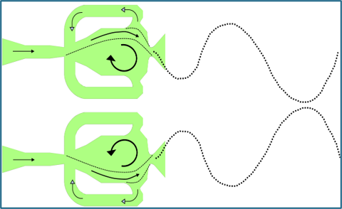
The self-induced oscillating jet is generated by a double-feedback fluidic oscillator.
The self-induced oscillating jet is generated by a double-feedback fluidic oscillator. This device does not include any moving parts and changes a steady jet to an oscillating jet by its simple design. The oscillating jet can be applied in different applications such as flow control and enhancing heat transfer as well as mixing.
When the supplied fluid passes through the mixing chamber, due to the Coanda effect, attaches to either wall of the chamber. A small part of the flow near the exit is diverted through the feedback channel and impinges the main jet at the inlet. This leads to the main jet at the chamber attaching to the opposite side, and the process is continued with a certain frequency.
y/dh = 3
z/dh = 0
y/dh = 8
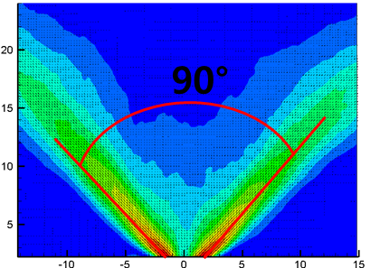
Free Oscillating Jet, Re=16,000
Two-dimensional time-resolved particle image velocimetry (TR-PIV) were carried out in confined and non-confined channels with a backward facing step while the inlet flow was an oscillating jet from a double feedback fluidic oscillator.
The effect of the step height and mass flow rate on the oscillating jet were examined.
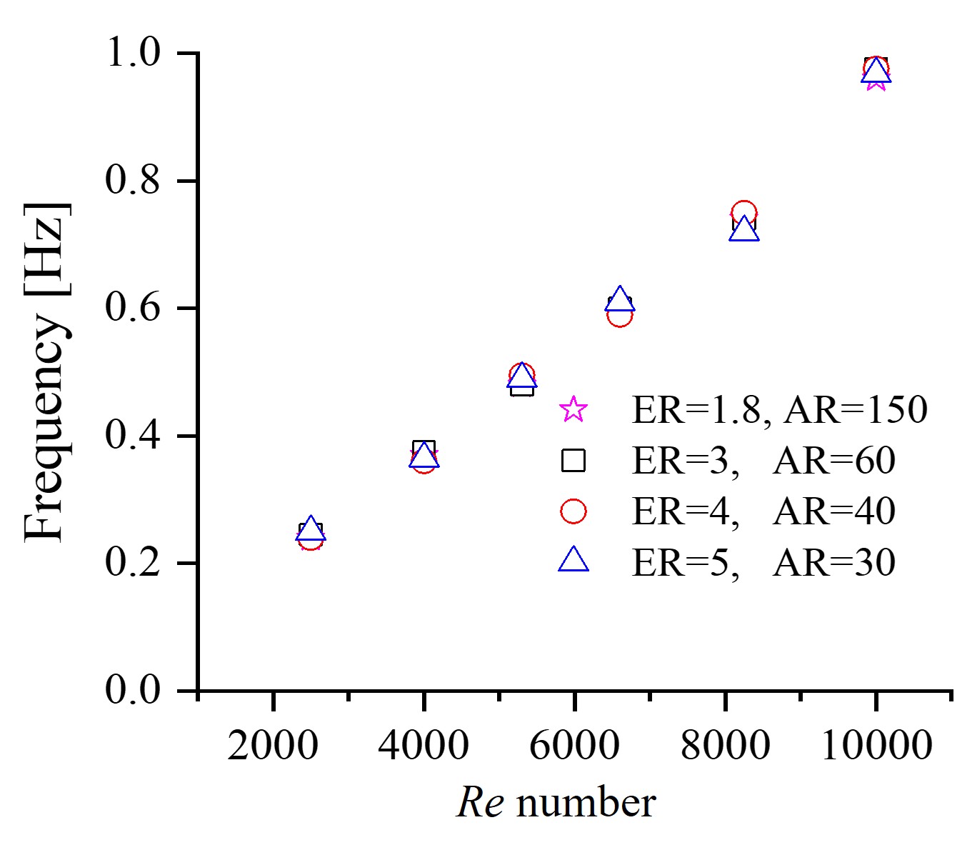
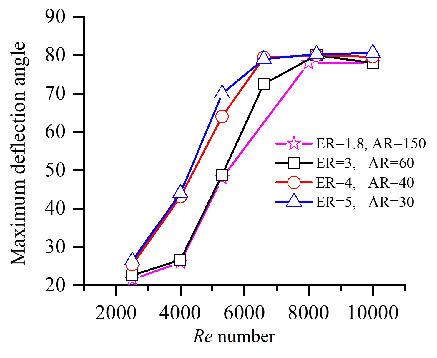
We found out that there is a linear relation between frequency and flow rate; However, deflection angle and flow patterns depend on the external domain, specially for low Reynolds numbers
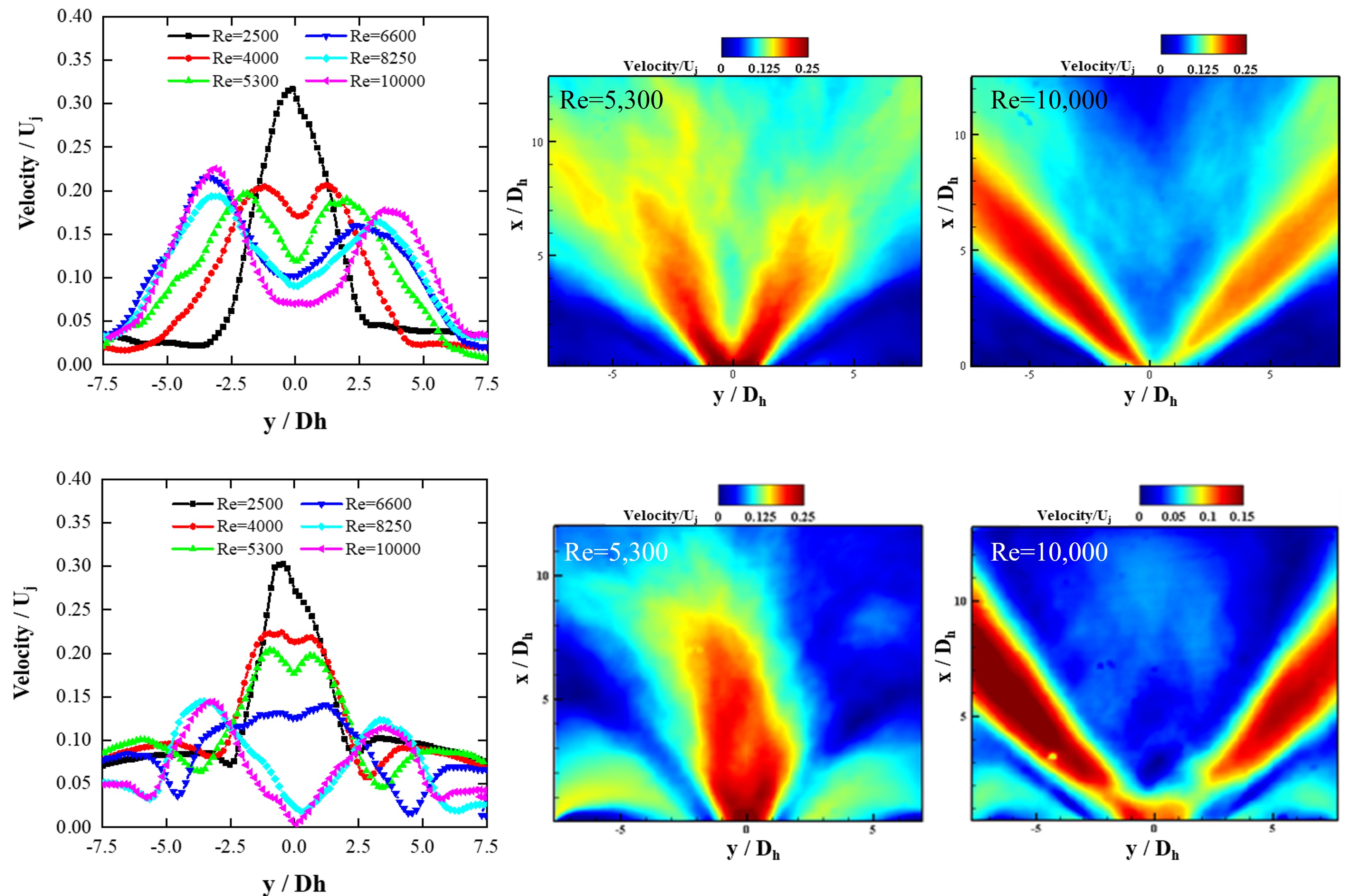
Increasing the Re number → peaks of velocity magnitude goes further away from the center line
Jets in cross flow have been very commonly used in industrial and engineering applications like cooling of turbine blades and combustion. When the jet is emitted in a cross flow, it bends over into the cross-flow direction, and due to the interaction of fluids, a complex vortical structure is created.
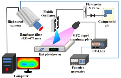
In low-speed wind tunnel, the smoke visualization is performed to study the flow characteristics of oscillating jet in cross flow.
Recf =0, Rej =16,000
Recf =2700, BR =0.99
Recf =2700, BR =0.99
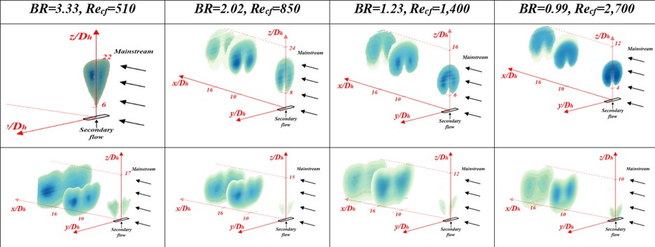
Time-averaged results of smoke visualization for JICF and OJICF
For current high-performance gas turbines, cooling of the turbine blades is of great importance. Since the turbine entrance gas temperature is higher than what the materials can withstand, film cooling or impingement cooling is widely applied for reducing the operating temperature. Jet impingement can also be applied in other industrial applications such as textile drying and electronic component cooling.
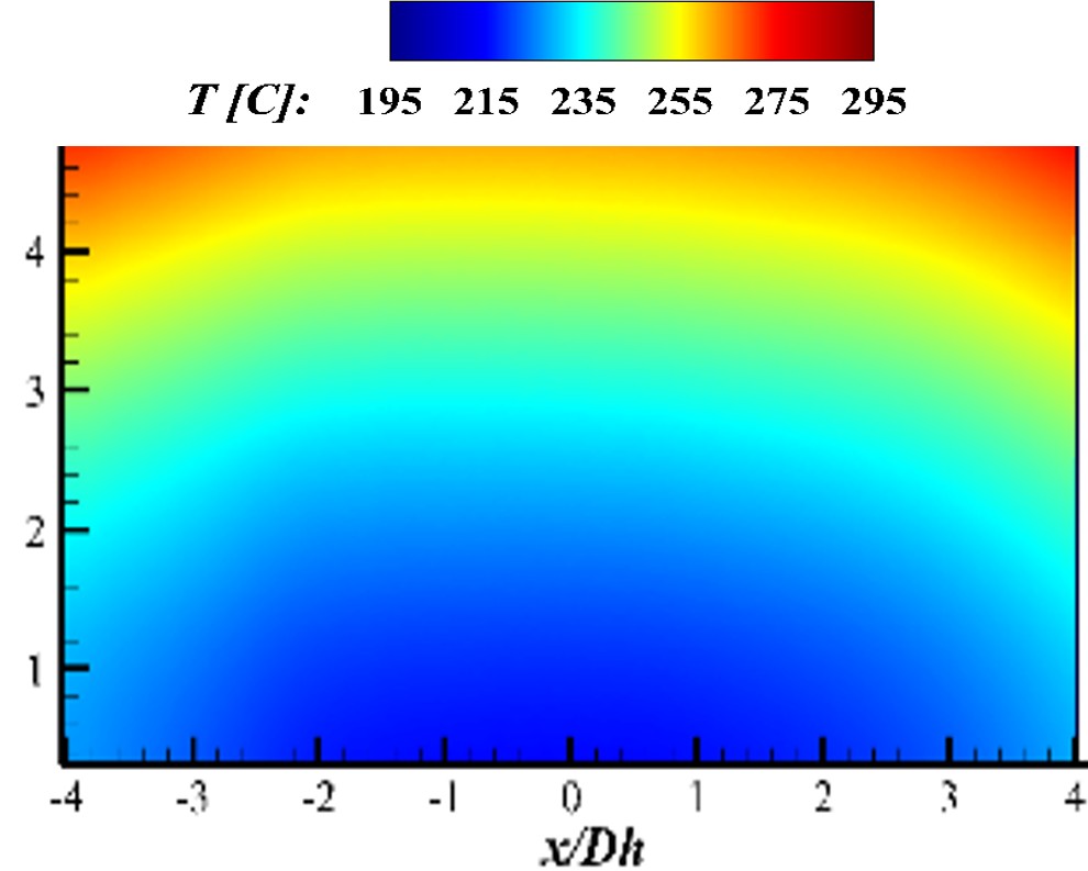
By thermographic phosphor thermometry technique, we showed that for impinging OJ in cross-flow, although the heat transfer is dominated by the cross flow, at constant Recf, the more Rej is, the more the Nusselt number is.